Kilobots
Repository
Mathematica Code this file has .nb extendion and can probably only be read properlly with Wolfran Mathematica
Kilobot - Final Project from Guilherme Klink on Vimeo.
Introduction
The kilobots are simplistic nano robots created by professor Mike Rubenstein that are able to communicate to each other through simplistic messages and vibrate their thin legs in order to move in flat surfaces. This project aims to use a swarm technique in order to deal with two drawbacks of the kilobots and give them a way to move accurately.
1 - No Encoders or External Feedback
Being very small robots do not allow the kilobots to have encoders or many sensors. Making knowing their position in the world or how much they move a challenge.
2 - Calibration
As the name suggest the kilobot are usually in the number of thousands. Obviously between each individual there small physical differences on its legs and actuators. The same amount of actuator activation will generate different angles in different kilobots.
Swarm Solution
To overcome these difficulties the robots will alternate their role between frame robot and moving robot. When on frame role the robot is responsible to synchronize with another two robots with the same role and create a local coordinate frame (see bellow). Then, on moving role the robot receive compute the distance from each other frame robot from a local frame and uses trilateration to calculate its position (x, y). For a 2D trilateration a point needs to know its distance to three other difference points of known coordinates, hence it will be required 3 robots to compose a local frame.
Creating a local frame
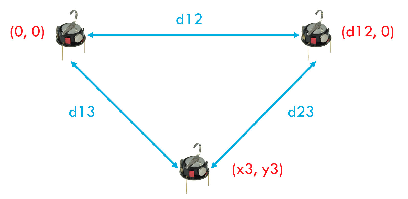
Kilobots are able to send messages containing an array of integers and estimate the distance d that the message traveled with a high precision. Using this messages a local frame can be created when three robots synchronize as the same frame and assume the function of:
- Frame origin: position x=0, y=0
- X-axis: position x=d12, y=0
- Another reference for trilateration: position x3, y3 will be calculated
Bellow you can see the math used to calculate the position x3 and y3.
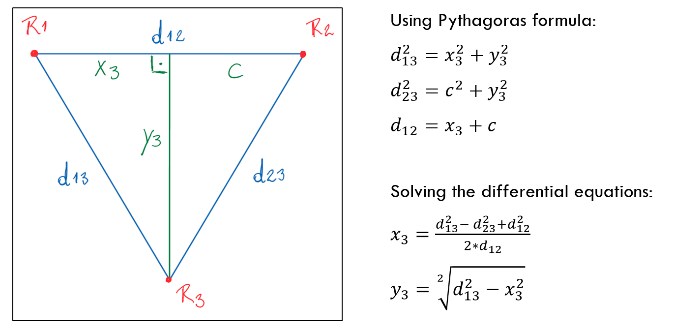
Trilaterate position

Once we obtain the distance to three known coordinates in the frame we can use the formulas found here to calculate the position (x, y) of the moving robot with respect to a local frame.
Calibration
Now that we can obtain the robots position we can talk about calibrating the kilobot turn. When a voltage is applied to the kilobot actuator, it vibrates the leg attached to it, making the robot turn in the opposite direction. The question becomes how much the actuator should be activated for an desired angle. Moreover, this value will be particular to each robot. The next steps shows how to calibrate a robot in the moving role.
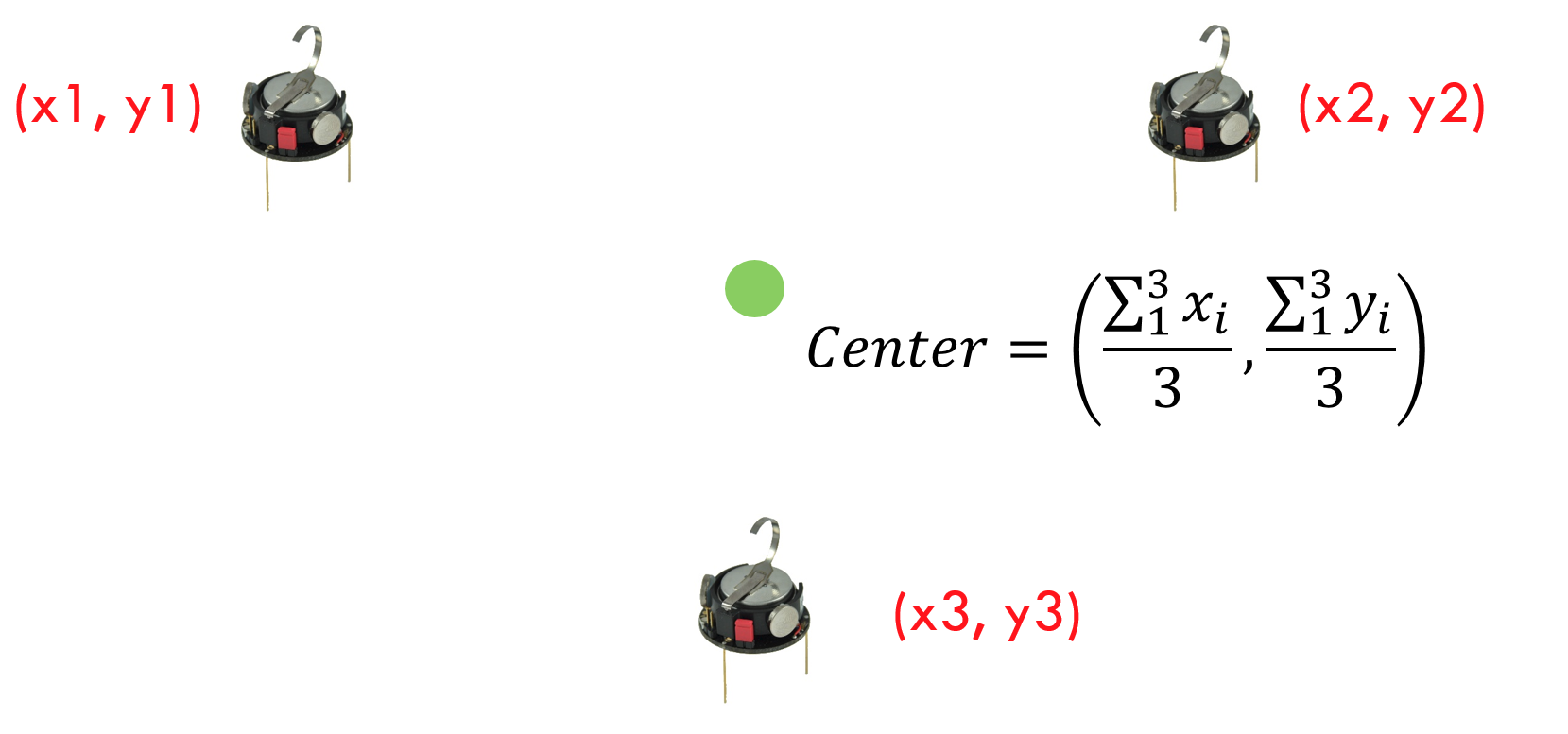
Center Reference
During the calibration process the robot will move towards the center of the local frame which will serve as the turn reference.
Calibration Step
Now that we have the coordinates of the robot and the center we can move the robot by small amounts and create a vector (the blue vector in the image bellow) in addition a vector can be generated from the robot position and the center (green vector).
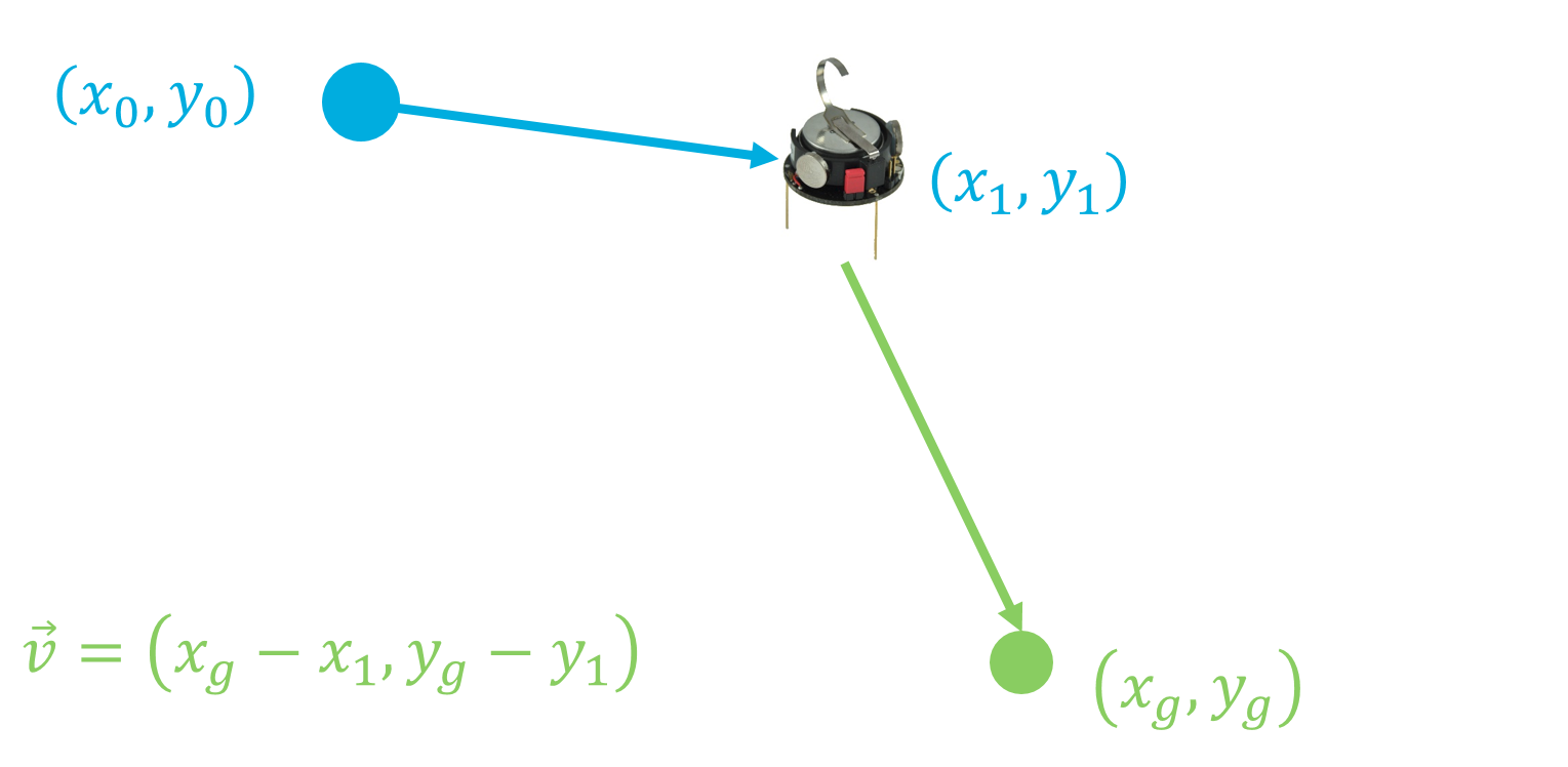
At anytime we can calculate the angle between two vectors using the formula bellow:
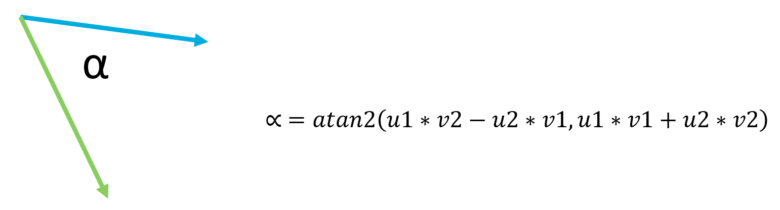
Hence we can figure the angle between “blue vectors” generated after turns and the angle required to move towards the center.
Turn Table
My software will apply different amounts of activation on the actuator as it does its best to move to the center and will record the activation and angle acquired. Once it reached the center the information recorded will be use to generate a regression that relates activation and angle. Now the robot is calibrated.